|
|
Embedded Systems - Model-Based Design
Stopwatch application (Simulink/Stateflow model)
Stage 1: Button presses and events
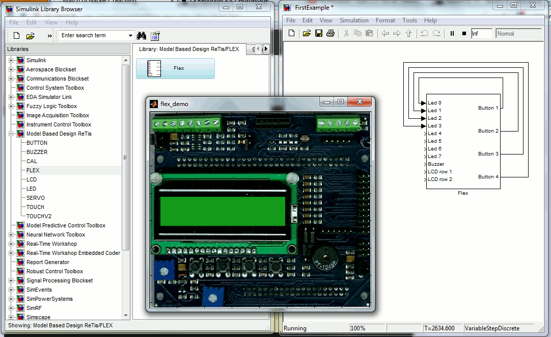
The first step in the creation of the model is the "Hello world" for our simulation environment.
Once Simulink starts, open the library browser and, from the group "Model Based Design Retis" take the Flex custom block.
then, connect the output buttons to the first four led inputs.
The resulting model can be simulated as in the Figure.

The code can be found here
Stage1.mdl
At simulation time, when pressing any one of the Flew buttons with the mouse,
the corresponding led on the Flex image will turn on.
Code generation
The description of the model modifications for code generation can be found here.
Stage 2: Managing the time
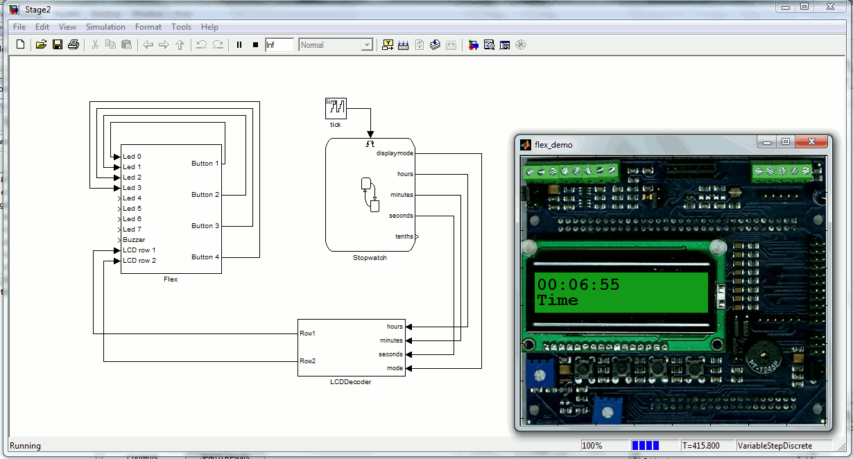
The second step is to add modeling elements that manages the time updates (the Stateflow block)
and the display of the time on the LCD screen (the subsystem LCD decoder).
The resulting model can be simulated as in the Figure.

The code can be found here
Stage2.mdl
Stage 3: The first simple state machine
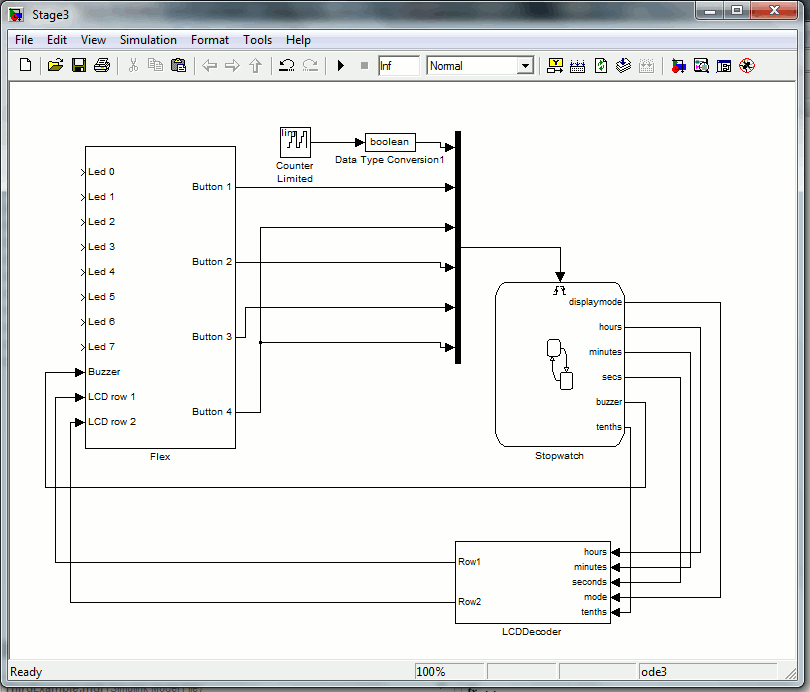
The third step adds the four main states of the stopwatch and some additional
functionality (hour updates in time set and Alarm set modes).
The resulting model can be simulated as in the Figure.

The code can be found here
Stage2.mdl
Stage 4: The full stopwatch application
This part is now up to you, remember that the full model for the stopwatch application must be brought to the exam and discussed.
|


